INDEX MAP (USE THIS IMAGE FOR INSTALLATION)
THIS MAPPING IS ONLY INTENDED TO
BE A "GUIDE". The routing and connection points you choose may be
different so feel free to be creative or adapt the kit to your specific
engine.

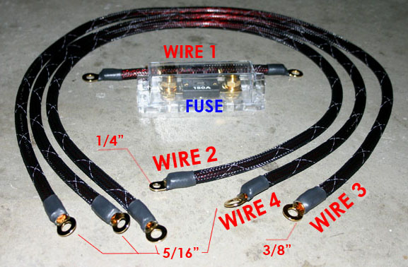
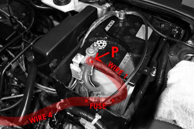
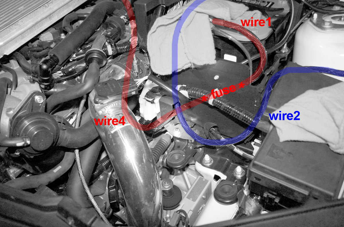
Wire1 =
Battery Positive (Bolt P) to Wafer Fuse
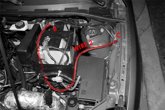
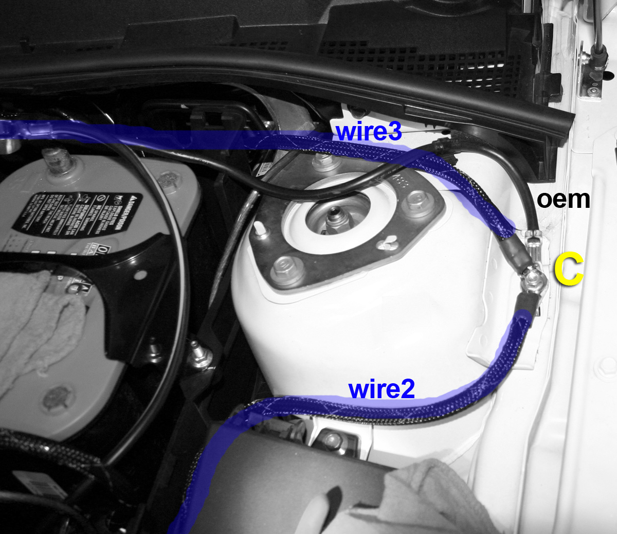
Wire2 =
Battery Negative (Bolt B) to OEM Chassis (Bolt C)
Wire3 =
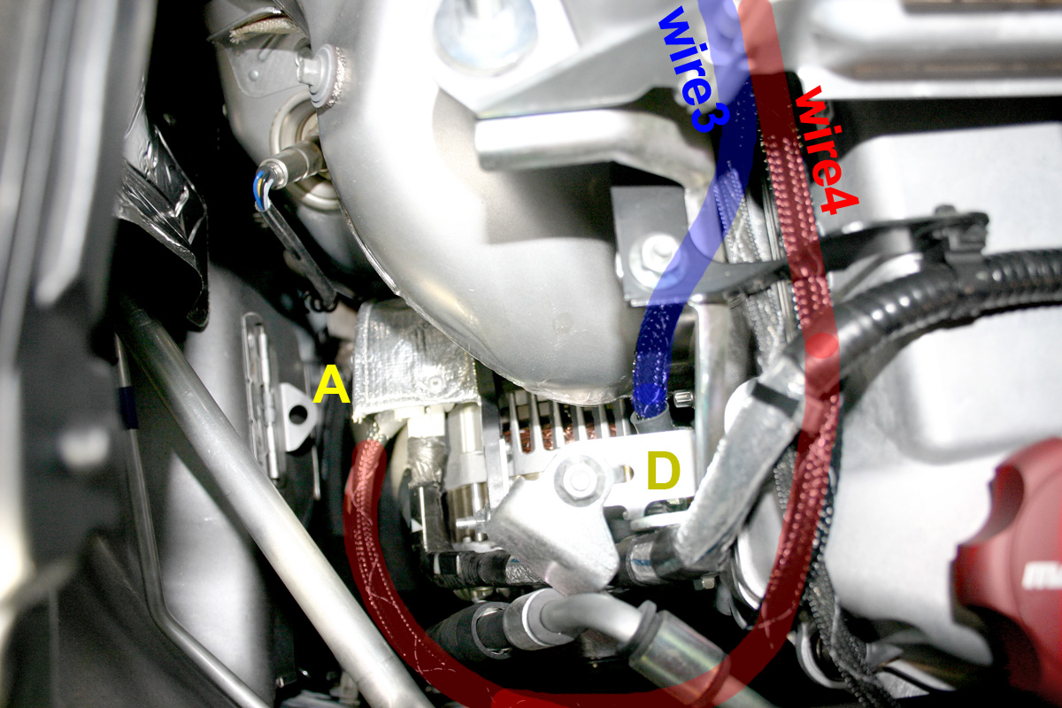
Engine Bracket above Alternator (Bolt D) to OEM Chassis (Bolt C)
Wire4 =
Wafer Fuse to Alternator Positive (Bolt A)
Note:
First connect wire 1 to the fuse and then wire 4 to the other end of the
fuse. The other end of wire 1 will connect to the positive battery
terminal. The other end of Wire 4 will connect to the positive alternator
terminal. (This is called Wire 1 + Wire 4). Don't connect the
fuse just yet and please disconnect the negative battery terminal so that
you don't cause an electric short and BLOW the fuse during installation.
Cover the terminals with a shop towel so you don't drop anything on the
terminals. Just use common sense and you will avoid un-wanted sparks.
Note:
The smallest ring connects to the negative battery. The largest ring
connects to point "D" which is the engine.
Note: Wires 3 and 4 go
OVER the engine block. This image shows a FMIC speed3. If you
have the STOCK speed3 then your wires will go UNDERNEATH the factory top
mount intercooler. Keep the wires away from the turbo and turbo
manifold. Secure wires with zip ties away from hot components if
applicable. These wires are HIGHLY abrasive resistant so it is ok to
have them touching plastic and metal edges. At connection points, you
may bend the ring terminals carefully to prevent the 4ga wire from having to
bend at too sharp of curves.