|
This is a 5 WIRE grounding kit walkthrough
(REV 2.0)
Mazda3 2.3L
(2004-2008) Hatchback and Sedan
Install time: 15-30
minutes |
| Note:
This kit will fit ALL mazda3's that have a 2.0L engine or
2.3L engine. For 2.0L
engine "i" model mazda3s, Connection Point "E" will be slightly different.
The mount for the engine cover screws off and
underneath is a stud that the mount screws too. Connect your ground wires
there and screw the mount back on (its attached to a nut that screws into
that stud). |
 |
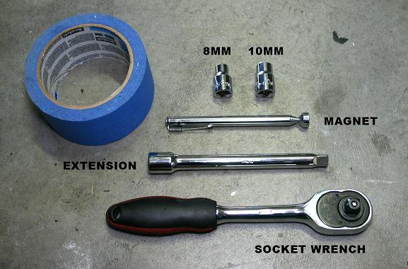
TOOLS REQUIRED:
 |
8mm and 10mm
socket wrench |
|
An extension
bar will help make removing the bolts easier |
|
Some tape to
protect the ring terminals so you don't short your battery. (connect
positive to negative on accident) |
|
A magnet will
help prevent you from dropping nuts or bolts into the engine |
|
Grounding Wires
with the right size ring terminals on the ends |
|
 |
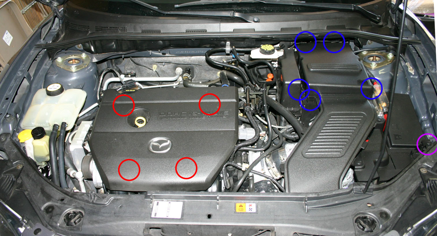
You will begin by popping the hood and removing the engine
cover. Just lift it vertically and it will release at the red circled
areas. These are the points of contact the cover has with the engine. |
 |
Then remove the battery cover next. There are tabs
circled in blue. The three tabs closest to the front of the car need
to be unlocked first. Then once you can lift the front of the battery
cover up, just pull it towards the front of the car.
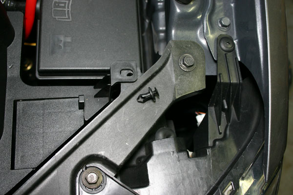
Remove the battery
vent. To do this you can use your finger nail or a Phillips screw
driver to help remove a plastic pin located near the front left head light.
The battery vent should lift right out of the car once this one pin is
removed. Note that there's a small arrow that marks the center of
the battery cover vent intake. This is to help you put the vent
back in. If you can't find the arrow then no big deal, there's only one
way to put the battery vent back in. |
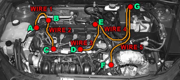
| INDEX DIAGRAM: |
 |
| |
 |
First sort the wires from smallest to largest. The smallest wire will
be WIRE 1, and the longest wire will be WIRE 5: Note that the smallest wire has terminals not facing up. This is on
purpose for a cleaner install. I've positioned the connectors to
perfection on every wire for the cleanest possible install. Also notice
that the two longest wires have smaller ring terminals on the end. These
two small ring terminals connect to the negative battery terminal.
The installation will begin with the smallest wire, and end
with the two longest wires.
|
 |
TIP: Use a magnet
so you don't drop any nuts or bolts when unscrewing.
If you don't have a magnet handy you can
just shove a towel around the work area so the nut has no where to fall.
Also if working on a HOT engine bay, the
bolts will be hot to touch.
SAFETY TIP: BEFORE working on your car any further, you may want to
DISCONNECT your negative battery terminal. This is to prevent any
electrical shorts while working in the engine bay. When I do this, I
like to WRAP the negative battery clamp in a thick towel so that they don't
come into contact with the negative battery terminal on accident.
For my installation I did not do this because I did not want to reset my
ECU. IF you reset your ECU, your engine will have to re-map and learn
its idle and set air/fuel ratios again. This causes erratic engine
behavior and rough idling. I wanted to FEEL the difference the
grounding kit made, not feel the ECU re-learning. :) |
 |
So now begins the installation.
Use a 10MM socket on NUT "A" and bolt "B". You may not want to tighten
any bolts or nuts all the way until all 5 wires are installed. This
way you can reposition the wires so they're routed the right way. This
also makes it convenient if you've put a wire in the wrong place and have to
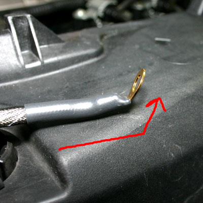
redo a wire. For your second smallest wire (Wire 2),
you are going to connect it to bolt B and fuel rail bolt "C". Now there
are two wires connected at point "B".

TIP: Bend the ring terminal connecting
to bolt "C" like the image below for a cleaner installation.
|
 |
The image on the left shows how
the smallest two wires will look after being installed.
These wires contain a highly durable sleeve that is resistant
to abrasion so feel free to route them however you want. It is OK for
these wires to touch the edges of plastics.
A word of Caution: Do not put these wires on a metal
part that gets really hot. (Such as the exhaust manifold) |
 |
Unscrew bolt "E".
Point "E" is located on a bronze looking plate attached to
the engine block. There are going to be TWO wires connecting to point:
Wire 3, and Wire 4.
When you connect Wire 4, make sure you are connecting the end
of the wire that has the large sized ring terminal. The smaller sized
terminal will connect to the negative battery.
Next, connect the other end of Wire 3 to the left fuel rail bolt "D". (Bend
the terminal so it fits cleanly like you did with the other fuel rail connection)
|
| In order to safely route the wires through the inside panel of the battery
box, you should wrap the ends with tape so that you don't accidentally touch ANY
part of the positive battery terminal. Even with tape on the terminals,
stay away from shorting the battery! View the thumbnail below to route Wires 4 and 5 through the SIDE hole and NOT
the hole facing the front of the car. There are MULTIPLE large holes
existing in the battery box. If you absolutely can not figure out a way to
make these two LONGEST wires fit you most likely put the wires through the
wrong hole in the battery box. If you know for certain there's no hole
on the side of the battery box, then you'll have to improvise and make your
own hole.
 This image on the left shows how to route the taped wires successfully.
Below shows the installation of Wires 3 thru 5.
| Wire 3 connects the engine grounding point "E" to
the driver side fuel rail "D" |
| Wire 4 connects the engine grounding point "E" to the negative battery terminal "G" |
| Wire 5 connects the throttle body "F" to the negative battery terminal "G" |
NOTE: Wire 5 can connect to the throttle body in ANY
of the bolts holding it in place. |
 |
| Pictured below shows how wire 4 is going to go through the SIDE of the
battery box to the negative terminal.
 |
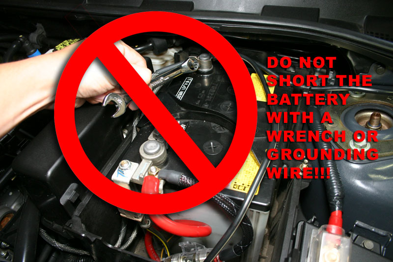 |
In the next step you will remove and install the small nut for the negative
battery terminal. Please be careful and don't connect the positive and
negative battery terminals accidentally with a solid metal wrench. I used a
rubber handled socket wrench and no extension bar. You may also use gloves
to do this. |
| Pictured below is the connection to the negative battery terminal. I put
the ring terminals on different sides of the battery clamp and then tightened
the nut with a socket wrench and NO extension. If you accidentally
disconnect the negative battery terminal, then you may reset your ECU and
lose your radio station presets. If you do reset
your ECU, don't blame the grounding wires for the way your engine behaves
after firing it up...

|
| After this final connection
point "G" - negative battery terminal, check and tighten all the nuts and bolts of every letter snug
and firm. Do not OVERTIGHTEN. Aluminum threads are SOFT and strip
easily. Make sure the wires are routed neatly and won't get in the way of
anything. Give the negative battery terminal a tug left
and right to see if you've properly secured it.
Reset your ECU if you want. Or don't do it to see if you'll notice the
improvement!
Reinstall the battery vent, battery cover and engine cover. Take your car for a test drive.
|