Congratulations and thank you for purchasing
the Flex Grounding kit! We believe we have put together the best grounding
kit for 06-07 WRX. This guide will take you step by step in installing our
kit as cleanly as possible in your engine bay.
Overview
Tools Required: Basic Metric Socket Set or wrench set. (Optional: wire
snips/cutter to cut ring terminals if you don’t want to remove certain bolts
all the way)
WARNING: Do not over tighten bolts. Aluminum is a SOFTER
metal than many realize so screws should be fastened “snug” and not overly
tight. If in doubt of your own strength, use a torque wrench along with
your owner’s manual suggested torque ratings.
Time for installation: 15 minutes to 1 hour depending on skill level.
Walthrough:
The wires are zip tied together in the order they
are to be installed. Lay the wires flat. You should see 1 small terminal and
2 big terminals at the ends. Start with the end that has the bigger
terminal, furthest from the small terminal (This is also the longest wire in
the kit). This is terminal "A"
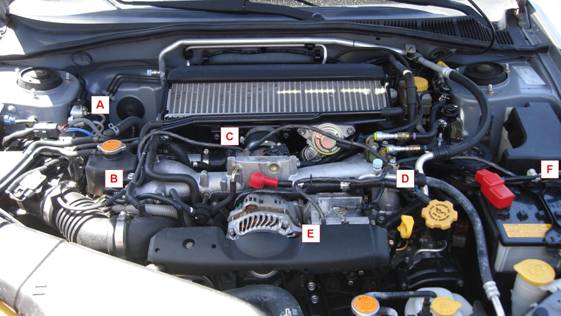
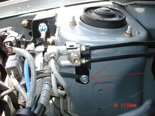
Locate this bolt on the passenger side strut
chassis "A". Remove this bolt. As with removing any bolt, take mental note
of how tight it is to loosen. Connect Terminal "A" through bolt. Tighten
bolt as tight as it was to loosen. Recommended wire routing shown.
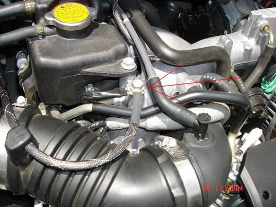
Connect other end to "B" driverside manifold. The
terminal that this wire is tied to also goes here.
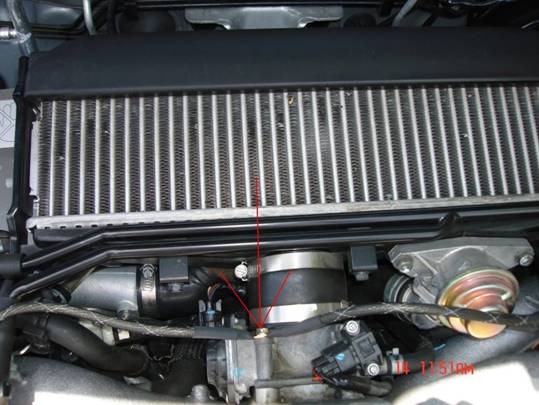
Next grounding point is "C" throttle body. This bolt does not remove fully
without moving the intercooler. Although you are welcome to do this, a
shortcut is to cut the terminals just wide enough to hook on to the bolt
once it has been loosened.
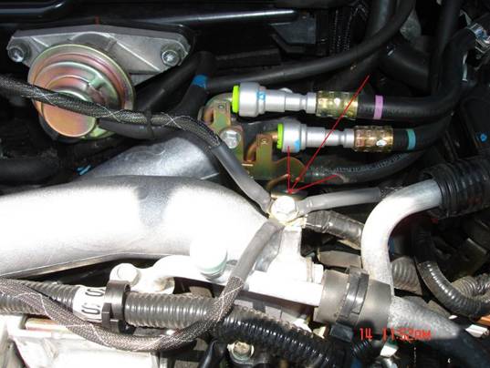
Next ground is "D" driver side manifold. Connect
all three terminals.
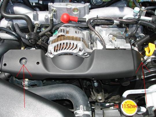
Remove the alternator cover with these 2 bolts
arrows are pointing at
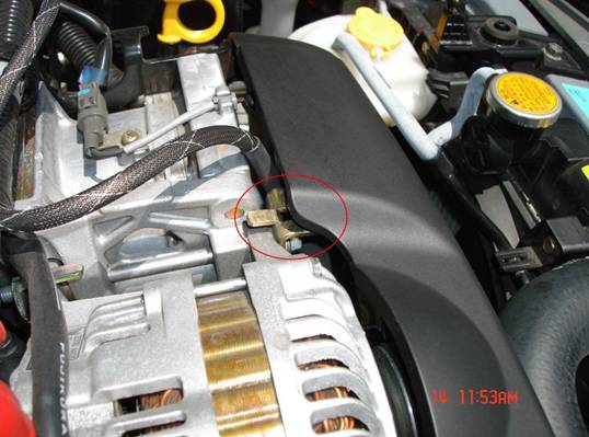
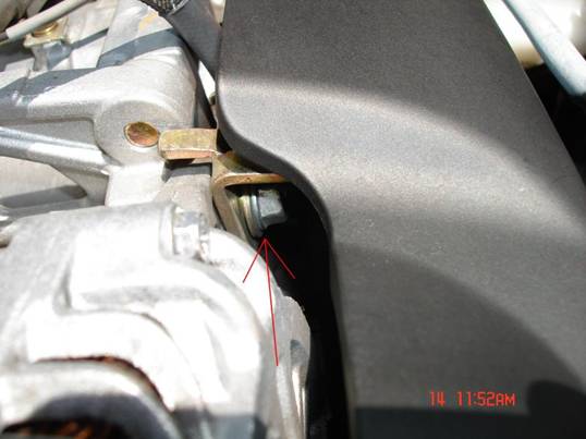
Once the cover has been removed, locate this
bracket. At this point, you should have two terminals left. This is where
the bigger of the two goes. Next ground is "E" alternator. Do not remove
this bolt all the way. Cut the connector just wide enough to hook on to this
bolt. once you've done this, put everything back together.
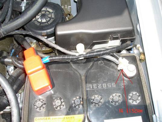
Finally, connect the smaller terminal to the
NEGATIVE terminal of the battery and button everything back up.
(CAUTION:
Make sure not to touch or go near the positive terminal) Install
alternator cover, double check bolts and wires aren’t loose, but don’t over
tighten them. Take for test drive.